
Views: 0 Author: Site Editor Publish Time: 2026-07-25 Origin: Site


Transitioning a metal component from prototype to high-volume production requires a manufacturing process that balances structural integrity, dimensional accuracy, and unit cost. The strategic shift from heavier metals like cast iron or steel to aluminum is driven by its exceptional strength-to-weight ratio, natural oxide-layer formation for water and corrosion resistance, and superior thermal conductivity. Engineering and procurement teams often struggle to align part geometry and performance requirements with the correct casting method and alloy, leading to excessive tooling costs, high defect rates, or delayed time-to-market. Evaluating aluminum casting for a production run requires a rigorous analysis of the specific casting methods, material properties, and the economic trade-offs between upfront tooling investment and long-term scalability.
Method dictates ROI: The choice between die, sand, or investment casting fundamentally alters the break-even point for production volumes and upfront tooling costs.
Alloy specificity drives performance: Selecting the correct alloy is non-negotiable; structural applications require different chemical compositions than thin-walled, high-detail enclosures.
Defect mitigation requires upfront DFM: Porosity and shrinkage are inherent risks in aluminum casting that must be mitigated through strict Design for Manufacturability (DFM) and vendor quality control protocols.
Total Cost of Ownership (TCO): True part cost must factor in post-casting machining, surface finishing, scrap rates, and the downstream logistics savings gained from aluminum's lightweight nature.
Defining what constitutes a successful casting run establishes the baseline for production quality. Success criteria typically include minimal internal porosity, strict adherence to geometric dimensioning and tolerancing (GD&T), and consistent metallurgical properties across batches. Achieving these metrics requires precise control over every phase of the manufacturing lifecycle. You cannot treat casting as a simple pour-and-cool operation. It is a highly controlled thermodynamic process where metal behavior changes drastically by the second.
The baseline workflow follows a strict progression from initial pattern creation to final inspection. Skipping or rushing any of these steps guarantees high scrap rates on the foundry floor.
Pattern and Core Production: Toolmakers machine a physical replica of the final part to create the mold cavity. For hollow parts, operators bake sand cores that sit inside the mold to form internal geometries.
Mold Assembly: Foundry workers prep the mold halves, apply refractory coatings to prevent the molten metal from soldering to the tool, and clamp the system shut.
Melting and Degassing: Raw aluminum ingots melt in a furnace. Operators must treat the liquid metal to remove impurities and dissolved gases before pouring.
Pouring and Solidification: The molten aluminum enters the mold cavity through a designed gating system. The metal cools and solidifies, taking the shape of the cavity.
Shakeout and Ejection: Once solid, the part is removed. Sand molds are broken apart and destroyed, while permanent metal molds open to eject the casting.
Fettling and Finishing: Operators cut away the gating systems, runners, and risers. The part then moves to heat treatment, abrasive blasting, or CNC machining.
Melting and pouring dynamics dictate the internal soundness of the final component. Molten aluminum behaves differently under atmospheric conditions compared to highly pressurized environments. You must address the absolute necessity of mitigating air contact during the melt. Exposure to ambient air causes rapid oxidation and hydrogen gas absorption. Foundries utilize rotary degassing techniques, plunging a spinning graphite rotor into the melt while injecting argon gas. The argon bubbles collect dissolved hydrogen and float it to the surface, preventing gas porosity from ruining the casting.
Solidification and cooling rates directly influence the mechanical properties of the finished part. The relationship between cooling speed and grain structure is absolute. Faster cooling yields finer microstructures, which translates directly to higher tensile strength and better fatigue resistance. Foundries strategically place cooling channels or metal chills within the mold to accelerate heat transfer in thick cross-sections. This localized cooling forces directional solidification, ensuring the metal freezes from the furthest points back toward the feed source, preventing internal shrinkage voids.
Casting is rarely the final step in the manufacturing process. Acknowledging post-processing requirements allows for accurate production planning. Operators must remove the gating systems used to feed the mold, often using band saws or trim dies. Many structural components undergo specific heat treatments, such as the T6 cycle. This involves solutionizing the part at high heat, quenching it rapidly in water, and artificially aging it in an oven to maximize yield strength. Finally, precision CNC machining achieves the tight tolerances required for critical mating surfaces, threaded holes, and sealing grooves.
Comparing the primary industrial casting methods requires evaluating them based on volume expectations, dimensional tolerance requirements, and available tooling budgets. No single method fits every engineering application. You must match the physical characteristics of your component to the strengths of a specific casting technology.
Casting Method | Ideal Production Volume | Dimensional Tolerance | Surface Finish (Ra) | Tooling Investment |
|---|---|---|---|---|
High-Pressure Die Casting | High (10,000+ units) | Excellent | Smooth (32-63 µin) | Extreme |
Permanent Mold (Gravity) | Medium (1,000 - 10,000 units) | Good | Moderate (125-250 µin) | Moderate |
Sand Casting | Low (1 - 1,000 units) | Fair | Rough (250-500 µin) | Low |
Investment Casting | Low to Medium | Exceptional | Very Smooth (63-125 µin) | High per unit |
High-pressure die casting pushes molten metal into a steel mold cavity at extreme velocities and pressures using a cold-chamber machine. This method is best for high-volume, thin-walled components requiring tight tolerances. It ensures extreme repeatability, creating thousands of parts virtually identical to the original steel mold. The rapid injection cycle allows for exceptional production throughput, often producing a part every few seconds.
The trade-offs involve significant capital expenditure. HPDC requires the highest upfront tooling investment due to the complex, hardened H13 tool steel molds needed to withstand the massive injection pressures. The turbulent nature of the injection process also makes parts susceptible to internal gas porosity. This trapped gas limits the viability of high-temperature heat treatments, as the expanding gas causes surface blistering and dimensional distortion.
Sand casting utilizes expendable molds formed by packing bonded sand around a reusable pattern. This method is best for low-to-medium volumes, massive parts, and complex internal cavities. Foundries use baked resin sand cores placed inside the main mold to create intricate internal passages, such as engine cooling jackets or pump volutes. The tooling investment remains relatively low because patterns can be cut from wood, polyurethane, or aluminum.
The primary trade-offs center around precision and finish. Sand casting delivers lower dimensional accuracy and rougher surface finishes. The granular nature of the sand transfers directly to the part surface. These factors almost always require extensive secondary machining operations to achieve functional tolerances on mating faces and sealing surfaces.
Permanent mold casting relies on gravity to fill a reusable metal mold, typically machined from cast iron or steel. This method is best for medium-volume production requiring high structural integrity and pressure tightness. The slower, gravity-fed filling process reduces turbulence, resulting in denser parts with minimal gas porosity. Because the metal cools rapidly against the steel mold, the resulting fine grain structure responds excellently to structural heat treatments.
The trade-offs sit between sand and high-pressure methods. Tooling is more expensive than sand casting patterns but significantly less than HPDC molds. The cycle times are slower than HPDC because the metal fills the mold via gravity and requires more time to solidify before the operators can safely eject the part.
Investment casting involves injecting wax into an aluminum die to create a pattern, coating that wax in a ceramic slurry, and melting the wax away in an autoclave to create a precise mold cavity. This method is best for highly complex geometries and exceptional surface finishes. It allows engineers to design parts without draft angles and consolidate multiple welded components into a single, unified casting.
The trade-offs are entirely financial and time-based. Investment casting carries a high cost per unit due to the labor-intensive, multi-step shelling process. Production cycles are lengthy. Manufacturers reserve this method for aerospace components, medical devices, or specialized industrial applications where machining from solid billet is impossible or cost-prohibitive.
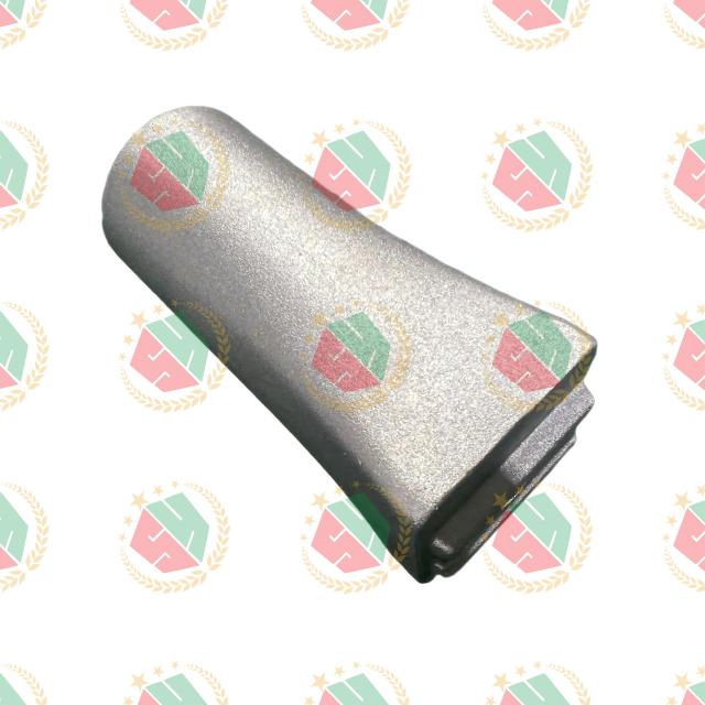
Matching alloy chemistry to performance outcomes is a mandatory engineering responsibility. You must evaluate dimensions such as yield strength, thermal conductivity, corrosion resistance, and machinability. The chemical composition dictates how the molten metal flows through the gating system, how it solidifies in the mold, and how it performs under mechanical stress in the field.
Alloy Designation | Primary Alloying Elements | Key Characteristics | Best Casting Method |
|---|---|---|---|
A356 | Silicon (7%), Magnesium (0.3%) | High strength, excellent ductility, heat-treatable | Sand, Permanent Mold |
ADC12 | Silicon (11%), Copper (2.5%) | Great fluidity, high hot-tear resistance, good machinability | High-Pressure Die Casting |
ZL102 | Silicon (10-13%) | Superior corrosion resistance, near-eutectic fluidity | Die Casting, Permanent Mold |
A356 aluminum casting parts dominate structural applications across multiple industries. This hypoeutectic alloy features excellent fluidity, high strength, and high ductility. The specific addition of magnesium allows it to respond exceptionally well to T6 heat treatment, which precipitates magnesium-silicide particles to drastically improve mechanical properties. It offers excellent resistance to hot tearing during the solidification phase.
Engineers specify this material for highly demanding environments. Ideal use cases include structural aerospace components, automotive engine blocks, and safety-critical suspension parts. The alloy provides the necessary toughness to absorb impact energy without catastrophic brittle failure, making it the go-to choice for load-bearing applications.
ADC12 aluminum casting parts represent the global standard for high-pressure die casting. This modified aluminum-silicon-copper alloy offers excellent machinability, dimensional stability, and resistance to hot tearing. The copper content improves high-temperature strength and hardness while maintaining good casting characteristics. The elevated iron content prevents the molten aluminum from soldering to the steel die casting molds.
Manufacturers rely on this alloy for mass production. Ideal use cases include electronic enclosures, automotive brackets, transmission housings, and complex consumer goods. It provides an optimal balance between raw material cost, ease of manufacturing, and functional performance for non-structural components that require intricate detailing.
ZL102 aluminum casting parts utilize a specific aluminum-silicon composition known for superior natural corrosion resistance. This alloy exhibits remarkable oxide-proof qualities, excellent castability, and high fluidity. The near-eutectic silicon content allows it to fill extremely thin wall sections without premature freezing, making it highly versatile for complex mold cavities.
This material excels in harsh environmental conditions. Ideal use cases include thin-walled components, marine hardware, and intricate architectural parts exposed to the elements. Engineers select it when pressure tightness, leak-proof performance, and long-term water resistance are strict functional requirements for the final assembly.
Calculating the true financial viability of a project requires a comprehensive framework. Overall value influencing factors extend far beyond the raw material cost per pound. You must analyze the interplay between initial tooling expenditures, production volumes, machining requirements, and expected scrap rates. A cheaper unit price often masks hidden costs in secondary processing or high defect rates on the assembly line.
Upfront tooling investment thresholds dictate the initial barrier to entry. You must compare the relatively low investment range of sand casting patterns against the massive capital expenditure required for hardened steel HPDC molds. Sand casting patterns utilize wood, plastic, or soft metals, allowing for rapid and inexpensive modifications during the prototyping phase. High-pressure die casting requires premium tool steel, extensive CNC machining, and complex thermal management channels, representing a massive upfront commitment that cannot be easily altered once cut.
Calculating volume break-even points dictates process selection. You must determine the exact production volume where the high tooling cost of die casting becomes more economical than the high piece-price of CNC machining or sand casting. At low volumes, the amortized tooling cost per part in HPDC is prohibitive. As volume scales into the tens of thousands, the rapid cycle times and minimal secondary machining of HPDC drive the unit cost down, easily offsetting the initial mold investment.
Design complexity exponentially increases tooling maintenance and unit costs. Features like undercuts, tight drafts, and complex coring require multi-part molds with moving slides, lifters, and hydraulic core pulls. These mechanical additions increase the initial tool build cost and introduce wear points that require frequent maintenance. Simplifying the part geometry through strict DFM directly reduces both the tooling complexity and the long-term unit price.
Maintain uniform wall thickness to prevent uneven cooling and shrinkage voids.
Apply a minimum of 2 to 3 degrees of draft to all vertical surfaces to allow for clean part ejection.
Eliminate sharp internal corners by adding generous fillets, which reduces stress concentrations and prevents hot tearing.
Design out undercuts wherever possible to avoid the need for expensive side-action slides in the mold.
Identifying common failure modes in the manufacturing process protects your production timeline. You must audit a manufacturing partner's ability to prevent these issues before cutting tooling. Quality control cannot be an afterthought; it must be engineered into the mold design and the foundry's daily operating procedures.
Defect Type | Visual Appearance | Root Cause | Foundry Mitigation Strategy |
|---|---|---|---|
Gas Porosity | Smooth, spherical voids inside the metal | Trapped air or dissolved hydrogen gas | Rotary degassing, vacuum casting, venting |
Shrinkage Porosity | Jagged, sponge-like cavities | Lack of feed metal during solidification | Optimized risers, metal chills, uniform walls |
Cold Shuts | Visible lines or cracks on the surface | Metal freezing before the mold is full | Higher pour temperatures, faster fill rates |
Inclusions | Dark spots or hard particles in the metal | Oxides or sand breaking into the melt | Ceramic filters in the gating system, fluxing |
Porosity and shrinkage defects are the most common causes of part rejection. You must differentiate between gas porosity and shrinkage porosity. Gas porosity occurs when trapped air or hydrogen bubbles form spherical voids during solidification. Shrinkage porosity appears as jagged, sponge-like cavities caused by uneven cooling and inadequate metal feeding. Mitigation strategies include vacuum-assisted casting, optimized gating design to ensure laminar flow, and strict atmospheric controls over the melting furnace.
Dimensional inconsistencies and warpage threaten the assembly process. Managing residual stresses during cooling and heat treatment prevents part distortion. When a casting cools unevenly, internal stresses build up. Subsequent machining or heat treatment can release these stresses, causing the part to warp out of tolerance. Foundries mitigate this by controlling quench rates, utilizing specialized straightening fixtures during the aging process, and stress-relieving the parts before final CNC machining.
Vendor evaluation requires strict criteria. Essential certifications like ISO 9001 or AS9100 demonstrate a baseline commitment to process control. You must verify their Non-Destructive Testing (NDT) capabilities. Require X-ray inspection to detect internal porosity, dye penetrant testing for surface cracks, ultrasonic testing for internal flaws, and comprehensive CMM dimensional reporting to verify GD&T compliance before approving full production.
Take the following actionable steps to advance your production planning:
Audit your 3D CAD models to ensure uniform wall thickness and a minimum of 2-degree draft angles on all vertical faces.
Initiate a Design for Manufacturability (DFM) review with a shortlisted casting partner to eliminate undercuts and optimize gating locations.
Specify your exact mechanical requirements and operating environment to the foundry before finalizing your alloy selection.
Establish a hard Acceptable Quality Limit (AQL) for porosity using ASTM reference radiographs.
Require a first-article inspection (FAI) report with full CMM dimensional verification before approving full production runs.
A: Aluminum delivers a superior strength-to-weight ratio, allowing engineers to shed massive amounts of weight from structural assemblies without sacrificing rigidity. The metal naturally forms a protective oxide layer upon atmospheric exposure, providing inherent resistance to water and harsh corrosive environments. Furthermore, aluminum melts at a significantly lower temperature than iron or steel. This lower melting point drastically reduces furnace energy consumption and shortens cycle times on the foundry floor, driving down overall production costs.
A: Foundries generally require a minimum run of 5,000 to 10,000 units to justify high-pressure die casting. This volume threshold exists because the process relies on complex, hardened tool-steel molds that require massive upfront capital investment. If your production run falls below this volume, the amortized tooling cost per part becomes economically unviable. For lower volumes, engineers should pivot to permanent mold or sand casting, which utilize significantly cheaper tooling materials.
A: Yes, but it depends entirely on the casting method. Components poured using sand or permanent mold techniques routinely undergo T6 heat treatments to maximize yield strength and hardness. Conversely, standard high-pressure die castings cannot undergo high-temperature heat treatments. The turbulent injection process traps microscopic pockets of gas inside the metal. If exposed to high heat, this trapped gas expands rapidly, causing the part surface to blister and destroying the component's structural integrity.
A: CNC machining excels at producing low-volume, ultra-precise components directly from solid billet. However, machining generates massive amounts of material waste and requires long cycle times per part. Casting scales economically for high-volume production. Once the mold is cut, a foundry can produce thousands of complex geometries rapidly with minimal material waste. Machining is typically reserved as a secondary operation to hit tight tolerances on specific mating surfaces of a cast part.
A: Porosity stems from two distinct sources: trapped gas and solidification shrinkage. Gas porosity occurs when molten aluminum absorbs hydrogen from ambient humidity or traps air during turbulent pouring. Shrinkage porosity happens when isolated pockets of liquid metal lack feed material as they cool and contract. Foundries prevent these defects by utilizing rotary degassing equipment, designing laminar-flow gating systems, and strategically placing metal chills in the mold to force directional solidification.
A: Alloys heavily alloyed with silicon and magnesium provide the highest levels of environmental durability. Materials like ZL102 and A356 are industry standards for their natural oxide-proof characteristics. The specific chemical composition of these alloys prevents deep oxidation, making them the primary choice for marine hardware, exposed architectural components, and automotive exteriors subjected to road salts and constant moisture.


