
Views: 0 Author: Site Editor Publish Time: 2026-07-31 Origin: Site


Transitioning a component from prototype to high-volume production requires strict adherence to metallurgical and manufacturing principles to avoid catastrophic tooling failures and cost overruns. Selecting the incorrect casting method, neglecting Design for Manufacturability (DFM), or misunderstanding the metallurgical realities of aluminum leads to high scrap rates, porosity, dimensional instability, and delayed time-to-market. Machining complex geometries from solid billet wastes material and consumes excessive machine hours. Aluminum and its alloys possess a relatively low melting point and exceptionally high fluidity. This makes the aluminum casting process ideal for achieving complex net-shape parts that would be impossible to machine efficiently. A systematic, engineering-led breakdown of this workflow equips procurement and engineering teams with the framework needed to evaluate foundry capabilities. You must align manufacturing methods with project constraints to ensure component viability.
DFM Dictates Economics: Up to 80% of a component’s structural integrity and final unit cost is locked in during the initial tooling design, pattern making, and mold flow simulation phases.
Process Control is Critical: Strict regulation of melting temperatures, degassing, and pouring velocity is required to mitigate inherent risks like hydrogen gas porosity and shrinkage defects.
Method Must Match Volume: The choice between die, permanent mold, and sand casting must be driven by a rigid evaluation of upfront tooling capital versus per-part production economics.
Post-Casting Requirements: Raw castings rarely meet final tolerance requirements; secondary operations like CNC machining and T6 heat treatment are mandatory for high-performance applications.
Establish baseline success criteria based on load-bearing requirements, tensile strength, thermal conductivity, and environmental exposure. Components operating in marine or harsh industrial environments face severe galvanic corrosion risks. These environments demand specific alloy chemistries with low copper content to survive long-term exposure. Engineering teams must evaluate the required yield strength and elongation percentages before selecting a material. You map specific aluminum alloys directly to these mechanical requirements. Recognize that alloy selection restricts the available casting methods.
For instance, A380 offers excellent fluidity and pressure tightness. This makes it the standard for high-pressure applications, but it performs poorly in gravity-fed sand molds. Conversely, A356 provides exceptional elongation and responds well to heat treatment. We use A356 heavily for structural permanent mold applications where failure is not an option.
Aluminum Alloy | Primary Alloying Elements | Best Casting Method | Key Characteristics |
|---|---|---|---|
A380 | Silicon, Copper | High-Pressure Die Casting | Excellent fluidity, good pressure tightness, poor anodizing response. |
A356 | Silicon, Magnesium | Permanent Mold / Sand | High strength, excellent corrosion resistance, heat treatable (T6). |
319 | Silicon, Copper | Sand / Permanent Mold | Good castability, excellent machinability, moderate strength. |
B390 | High Silicon | Die Casting | Exceptional wear resistance, low ductility, difficult to machine. |
Analyze the break-even point between high upfront tooling costs and lower per-part costs. Hardened steel dies require significant initial capital investment, extensive machining time, and rigorous thermal treatments. You must establish production volume thresholds to justify the transition from low-volume sand casting to high-volume automated systems. Low production volumes rarely justify the expense of complex steel tooling. Expendable mold processes remain more viable for short runs. High volumes demand rapid cycle times to amortize tooling expenses effectively across tens of thousands of units. Calculating the amortization curve early in the project lifecycle prevents catastrophic budget overruns. It aligns the manufacturing strategy with actual market demand.
1 to 1,000 Units: Utilize sand casting or investment casting. Tooling costs are minimal, relying on wood or plastic patterns.
1,000 to 10,000 Units: Transition to permanent mold casting. Cast iron or steel molds offer better surface finishes and tighter tolerances without the extreme cost of high-pressure dies.
10,000+ Units: Implement high-pressure die casting. The massive upfront cost of H13 tool steel dies is offset by cycle times measured in seconds.
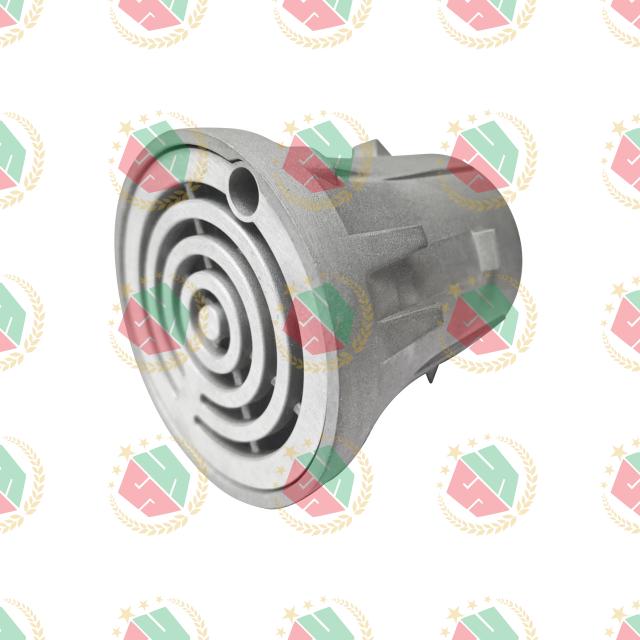
Evaluate component geometry for castability during the initial design phase. Focus on implementing adequate draft angles. We typically specify between one and three degrees of draft on exterior walls to allow clean ejection from the mold cavity. Interior walls often require slightly more draft due to the aluminum shrinking onto the core as it cools. Maintain uniform wall thicknesses throughout the part. Thick, isolated sections create hot spots that lead directly to shrinkage voids. Eliminate sharp internal corners by adding generous fillets. A minimum fillet radius of 0.125 inches reduces severe stress concentrations during the rapid solidification phase. Utilize advanced mold flow and thermal simulation software to predict cooling rates accurately. This software helps engineers identify potential shrinkage zones before cutting any steel. Simulation data drives the design of optimal gating and riser systems. It ensures molten metal reaches every extremity of the cavity before freezing.
Select mold materials based on the chosen process and expected production lifecycle. Use premium H13 tool steel for high-pressure applications to withstand extreme thermal shock and injection pressures. Utilize silica sand mixed with chemical binders for expendable sand molds. Develop precise physical patterns to form the exterior mold cavity. You must account for the specific volumetric shrink rate of the selected aluminum alloy, which is typically around 5/32 inch per foot. This shape-making phase dictates the baseline dimensional accuracy of the final part. Design and integrate expendable sand cores for complex internal geometries. Hollow cavities and internal undercuts are often required for specialized components. For example, manufacturing a custom aluminum floor drain casting requires precise core placement to form the internal water trap geometry.
Calculate the precise charge mixture of raw materials to achieve the target metallurgical chemistry. Combine prime aluminum ingots, clean manufacturing scrap, and specific alloying agents like silicon, copper, or magnesium. These hardeners dictate the final mechanical properties and fluidity of the melt. Bring the furnace to the optimal pouring temperature. We generally hold the melt between 1200°F and 1400°F, depending on the specific alloy grade. Execute rigorous degassing protocols using rotary impellers. These devices inject argon or nitrogen gas directly into the melt. The rising gas bubbles catch dissolved hydrogen and carry it to the surface. Implement strict fluxing procedures to separate oxide impurities and dross from the clean molten metal. Skim the surface thoroughly to ensure a high-quality pour.
Compare gravity-fed pouring mechanisms against highly pressurized injection systems. Gravity systems utilize automated ladles to transfer metal into the filling chamber. They rely on the natural weight of the metal to fill the void. Pressurized systems are fundamental to the aluminum casting process in high-volume environments. They use cold chamber configurations where a hydraulic plunger forces metal into the die at extreme velocities, often exceeding 100 inches per second. Implement careful, time-based pressure regulation across all methods. Low-pressure permanent mold systems achieve this by pressurizing the furnace chamber directly on top of the molten metal surface. This pushes fluid up a stalk into the mold. Control injection velocity meticulously to ensure the whole interior of the mold is filled completely while minimizing turbulence and air entrapment.
Manage thermal gradients within the mold to promote directional solidification. The casting must freeze progressively from the thinnest sections toward the thickest sections. This directional freezing draws molten metal from strategically placed risers. The risers compensate for natural volumetric shrinkage as the aluminum transitions from liquid to solid. Utilize localized cooling channels within permanent steel molds. We pump water or thermal oil through these lines to accelerate freezing in massive cross-sections. Execute automated or manual ejection protocols precisely once the part reaches structural rigidity. Use strategically placed ejector pins to push the part out of the cavity simultaneously. Proper pin placement removes the part without causing dimensional distortion, bending, or surface galling.
Remove excess material mechanically using trim dies, band saws, or CNC routers. This wrap-up phase includes cutting away gates, runners, risers, and any parting line flash that seeped between mold halves. Apply surface finishing techniques tailored to the end-use environment. Shot blasting creates a uniform matte texture. Powder coating or anodizing provides robust environmental protection. Proper finishing achieves the required aesthetic and corrosion resistance for exposed architectural parts, such as an aluminum floor drain lid. Execute thermal processing to manipulate the microstructure. The T6 heat treatment involves solutionizing the part at high temperatures, quenching it rapidly in water, and artificially aging it. This maximizes the yield strength and surface hardness of the final component.
High-pressure die casting is optimal for high-volume production runs exceeding 10,000 units annually. It excels at producing exceptionally thin walls, complex details, and tight dimensional tolerances straight out of the mold. The primary trade-off involves the highest initial tooling capital. You need massive hardened steel dies to withstand injection pressures that can reach 10,000 PSI. Parts produced via this method are highly susceptible to internal gas porosity caused by turbulent filling. This inherent porosity makes standard die-cast components generally unsuitable for T6 heat treatment. Trapped gas expands and blisters the surface during thermal processing.
Permanent mold casting is ideal for medium-volume production requiring dense, highly sound microstructures and excellent pressure tightness. The slower, gravity-fed or low-pressure filling minimizes turbulence. This drastically reduces trapped gas. We frequently utilize this method for manufacturing critical infrastructure components, such as an aluminum casting flange designed for high-stress fluid transfer systems. Trade-offs include moderate tooling costs and significantly slower cycle times compared to high-pressure systems. The process is also limited to simpler exterior geometries unless expendable sand cores are integrated. Using sand cores creates a semi-permanent mold setup for complex internal cavities.
Sand casting offers the lowest barrier to entry regarding tooling costs. It utilizes inexpensive wood, plastic, or machined aluminum patterns. It is highly scalable for low-volume runs, massive industrial components, or highly intricate geometries that cannot be ejected from rigid steel dies. Investment casting utilizes expendable wax patterns coated in ceramic, offering superior detail for complex shapes. The primary trade-offs for sand casting include a rougher surface finish. This often requires extensive secondary machining. Production rates are substantially slower. Overall dimensional accuracy is lower due to the shifting nature of the sand mold during pouring and solidification.
Casting Method | Ideal Production Volume | Initial Tooling Cost | Surface Finish Quality | Internal Porosity Risk |
|---|---|---|---|---|
High-Pressure Die Casting | 10,000+ units | Very High (Hardened Steel) | Excellent (Smooth) | High (Turbulent Fill) |
Permanent Mold (Gravity) | 1,000 - 10,000 units | Moderate (Cast Iron/Steel) | Good | Low (Laminar Fill) |
Sand Casting | 1 - 1,000 units | Low (Wood/Aluminum Patterns) | Poor (Requires Machining) | Moderate (Moisture/Gas) |
Trapped gas and oxide films severely compromise the mechanical integrity of the casting. They lead directly to premature fatigue failure. Gas porosity appears as smooth, round bubbles on a machined surface. Shrinkage porosity manifests as jagged, irregular voids. Mandate strict melt temperature controls to prevent overheating. High temperatures exponentially increase hydrogen absorption in liquid aluminum. Enforce routine rotary degassing to pull hydrogen out of the melt before pouring. Use vacuum-assisted technologies in high-pressure environments to evacuate air from the die cavity just milliseconds before injection. Implement ceramic foam filters in the gating system. These filters catch hard oxide inclusions before they enter the main part cavity.
Warping, distortion, or internal voids are caused by uneven cooling rates and inadequate feeding during the critical liquid-to-solid transition. Thick cross-sections cool slower than thin walls. This creates internal stresses that pull the part out of tolerance. Require foundries to provide predictive thermal modeling during the DFM phase to identify these problem areas. Utilize localized mold cooling channels, often called chill blocks, to force rapid solidification in massive sections. Apply Chvorinov's rule when designing risers. Ensure the riser remains liquid longer than the casting section it is designed to feed. This draws liquid metal into the shrinking zone, eliminating voids.
Project delays frequently occur due to the 8-to-16-week average lead time required to machine, harden, and validate complex steel tooling. Tooling modifications after cutting steel are expensive and time-consuming. Implement a phased prototyping approach to mitigate this risk entirely. Use 3D printed sand molds to cast physical prototypes in the exact production alloy. This allows engineering teams to validate the design, test mechanical properties, and confirm assembly fits before committing capital to permanent steel tooling. Establish clear milestones for T0 (first off tool), T1, and T2 sample validation phases. This keeps the project timeline on track and holds the foundry accountable.
Common Defect | Visual Identifier | Root Cause | Corrective Action |
|---|---|---|---|
Gas Porosity | Smooth, spherical voids. | Dissolved hydrogen in the melt. | Increase rotary degassing time; lower melt temperature. |
Shrinkage Voids | Jagged, irregular cavities. | Inadequate feeding during solidification. | Redesign risers; add chill blocks to thick sections. |
Cold Shuts | Distinct lines or cracks on the surface. | Metal freezing before the mold fills completely. | Increase pouring temperature; optimize gating velocity. |
Inclusions | Hard, dark spots in the metal matrix. | Oxides or dross entering the mold. | Implement ceramic foam filters; improve furnace skimming. |
Successful aluminum casting is not a commodity purchase. It is a highly engineered process where the alignment of component geometry, alloy selection, and casting methodology dictates project viability. Prioritize manufacturing partners that offer transparent, in-house DFM services. They must utilize advanced mold flow simulation and maintain rigorous, documented metallurgical testing standards. Moving forward, execute the following steps to ensure project success:
Compile existing CAD files and explicitly define critical tolerance zones and mating surfaces.
Define annual volume requirements to narrow down the most economically viable casting method.
Request a preliminary DFM audit from shortlisted foundries to identify geometry risks early.
Obtain a detailed tooling cost breakdown, including core replacements and maintenance schedules.
Validate initial designs using rapid prototyping or 3D printed sand molds before cutting permanent steel.
A: Aluminum offers a relatively low melting point and excellent fluidity, allowing it to fill intricate mold cavities easily. It provides a high strength-to-weight ratio, excellent thermal conductivity, and natural corrosion resistance. These inherent material properties make it highly versatile for automotive, aerospace, and industrial applications requiring lightweight, durable components.
A: Sand casting is generally the most cost-effective method for low-volume runs. The tooling relies on inexpensive materials like wood, plastic, or machined aluminum patterns rather than hardened steel dies. This significantly lowers upfront capital requirements, making it ideal for prototypes, massive parts, and small production batches.
A: Tooling design dictates exactly how molten metal flows and cools. Proper gating and risers prevent turbulence and eliminate shrinkage voids. Accurate pattern making accounts for the specific volumetric shrink rate of the alloy, ensuring the final cast part meets precise dimensional tolerances after complete solidification.
A: Porosity is caused by trapped hydrogen gas, moisture in sand molds, or air entrained during turbulent pouring. Foundries prevent it by degassing the molten metal with argon or nitrogen. They also optimize gate design to ensure laminar flow and utilize vacuum-assisted systems to evacuate air from rigid dies.
A: Raw castings cannot match the ultra-tight tolerances of CNC machining. While high-pressure die casting achieves excellent near-net shapes, critical mating surfaces, threaded holes, and precise bearing fits always require secondary CNC machining operations to meet final engineering specifications.
A: Lead times vary heavily based on the chosen process. Sand casting patterns can be produced in 2 to 4 weeks. Complex hardened steel dies for high-pressure die casting typically require 8 to 16 weeks for design, CNC machining, heat treatment, and initial sample validation.
A: A356 is highly regarded for its excellent combination of strength, ductility, and corrosion resistance, especially when subjected to T6 heat treatment. It is widely used in structural automotive components, marine hardware, and pressure-tight fluid handling systems.


