
Views: 0 Author: Site Editor Publish Time: 2026-10-26 Origin: Site


Finding a critical design flaw after purchasing a steel mold is a costly nightmare for any engineering team. Imagine signing off on a $50,000 tool steel mold. You wait eight weeks for fabrication. Then, you discover the very first cast part fails to fit into the main assembly because of an unforeseen friction point.
Modern CAD software is incredibly powerful. Yet, it cannot perfectly mimic real physical stress, assembly friction, or tactile ergonomics. Moving directly from a digital screen to hard tooling carries immense financial risk. Prototype manufacturing solves this problem before tooling begins. It acts as an essential bridge between digital design and mass production.
In this comprehensive guide, you will learn exactly how to validate cast part designs through physical prototyping. This rigorous approach ensures your transition to mass production remains seamless and cost-effective.
Risk Mitigation: Physical validation prevents costly errors during final tooling by identifying critical design flaws early in the engineering cycle.
Material Simulation: Advanced subtractive methods can closely replicate the mechanical properties, weight, and thermal resistance of final cast metals.
Comprehensive Testing: Tangible test units allow engineering teams to rigorously validate dimensional accuracy, assembly fit, and real-world functional performance.
Supplier Vetting: Choosing the right prototyping partner is just as critical as the design itself to ensure a smooth transition to mass production.
Cost Efficiency: Investing a small fraction of the budget in a high-quality prototype saves exponential costs in future mold modifications and production delays.
In the industrial manufacturing sector, moving directly from a digital design to hard tooling is a high-risk strategy. Recent industry analyses highlight a growing shift towards agile hardware development. Global supply chain pressures are mounting. Consequently, manufacturers are increasingly integrating rapid prototyping cycles to compress time-to-market. Validating designs through physical iterations has transitioned from an optional luxury to a mandatory risk management strategy.
Die casting molds are typically machined from hardened tool steel. These tools are specifically engineered to withstand extreme thermal and mechanical fatigue. If a cast part fails after the mold is created, modifying that tooling is exceptionally difficult. Technical staff must rely on electrical discharge machining, welding, or complete tool remanufacturing. This process not only costs tens of thousands of dollars but can also delay product launches by several months. Creating a physical test part acts as an insurance policy. It verifies the geometry before any steel is cut for the final mold.
Rapid prototyping takes a design from a theoretical 3D model to a tangible object. Engineers can handle, test, and stress this physical unit. It translates digital assumptions into physical realities. Putting a real part in the hands of a mechanical engineer exposes manufacturing challenges that software algorithms might easily overlook.
Modern CAD and Finite Element Analysis software are indispensable tools. However, they have distinct limitations. Digital simulations often assume perfect material isotropy and uniform thermal dynamics. In reality, physical parts experience unpredictable friction during assembly. They suffer unexpected thermal warping and complex fluid dynamics that software cannot perfectly replicate. A physical model reveals these hidden variables immediately.
Beyond engineering validation, physical prototypes serve a critical business function. Having a tangible, validated model accelerates final stakeholder approval. It provides executives and investors with physical proof of concept. This tangible evidence secures the necessary funding and confidence to authorize expensive mass production tooling.
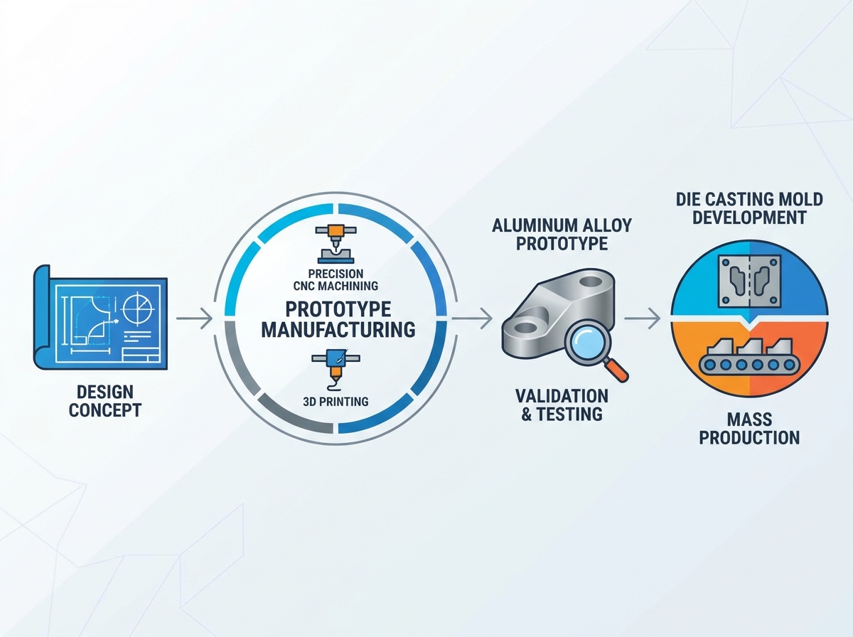
Selecting the correct prototyping technology depends entirely on the specific validation requirements of your project. Design teams must evaluate whether they need quick visual confirmation, rigorous mechanical testing, or low-volume functional field trials.
3D printing is frequently utilized for rapid, early-stage visual validation. Stereolithography provides excellent surface finishes for aesthetic reviews. Selective Laser Sintering offers durable plastic components. Direct Metal Laser Sintering can print metal structures. However, the metallurgical grain of 3D-printed metal differs significantly from cast metal. This structural difference somewhat limits its utility for highly rigorous mechanical testing.
For validating metal cast components, custom CNC machining remains the industry gold standard. By milling a prototype directly from a solid billet of metal, engineers obtain a near-exact replica of the final cast part. The weight, strength, and structural integrity match closely. Furthermore, this subtractive method allows for intense functional testing under real-world load conditions. It ensures the design will perform exactly as intended once mass-produced.
When the validation process requires testing a batch of fifty to one hundred parts, rapid tooling is highly effective. This involves creating soft molds from silicone used for urethane casting or softer metals like P20 steel and aluminum. These soft molds degrade quickly and cannot handle high-volume production. Still, they provide enough prototype units to conduct extensive field testing and assembly line trials.
To accurately predict how a metal cast part will behave in the field, the test unit must possess equivalent mechanical fidelity. Subtractive manufacturing provides the most reliable pathway to achieving this parity. The closer the prototype matches the final production material, the more reliable the testing data becomes.
The most effective way to test a metal cast part is by using solid metal. Machining allows engineering teams to utilize the exact alloy that will be poured during final production. Alternatively, they can use a highly comparable equivalent. Consequently, yield strength, tensile strength, and thermal conductivity metrics remain highly consistent between the prototype and the final product.
Cast parts inherently experience shrinkage and cooling distortion. This physical reality makes extremely tight tolerances difficult to maintain without secondary operations. Utilizing precision CNC machining parts allows engineers to test the strictest tolerances of their design. By evaluating the machined model, teams determine if these tight tolerances are functionally necessary. If they are not, the tolerances can be relaxed for the casting process. Relaxing non-critical tolerances significantly reduces mass production costs and minimizes defect rates.
Material selection dictates long-term performance. For instance, creating aluminum alloy CNC machined parts using specific grades like 5019-H112 allows engineers to simulate exact physical stress. A high-precision irregular pipe clamp bracket machined from this alloy will reveal exactly how the part handles vibration and torque. Specifically, testing these materials confirms that the chosen alloy possesses the appropriate corrosion resistance, weight-to-strength ratio, and thermal dissipation properties required for the final application.
Once the physical model is manufactured, a structured validation process must begin. Engineers conduct a series of tests categorized into form, fit, and function. This rigorous approach ensures comprehensive design verification before moving to the tooling stage.
Form validation focuses on the physical appearance and manufacturing feasibility of the part. Engineers evaluate whether the aesthetics align with the overall product vision. More importantly for casting, they analyze the geometry for Design for Manufacturability. They must verify that wall thicknesses are uniform to prevent cooling porosity. They also ensure that appropriate draft angles are integrated, even if the prototype was machined from a billet.
Mechanical components rarely operate in isolation. Fit validation ensures the prototype mates seamlessly with all adjacent components in the assembly. Picture a senior engineer meticulously testing threads, snap-fits, alignment pins, and bolting locations on the shop floor. This phase identifies tolerance stack-up issues. It guarantees zero physical interference when the complete product is assembled.
Function validation is the most rigorous phase. It subjects the prototype to the actual harsh conditions it will face in the field. This includes drop tests for impact resistance. Engineers run thermal cycling in environmental chambers to check for expansion warping. They execute fluid pressure tests for sealed pump housings and sustained load-bearing tests to identify structural weak points.
Validation Phase | Key Metrics Evaluated | Common Testing Methods | Acceptance Criteria |
|---|---|---|---|
Form | Aesthetics, Draft Angles, Wall Thickness | Visual Inspection, Caliper Measurement | Matches CAD specifications; visually free of defects; uniform walls. |
Fit | Mating, Tolerance Stack-up, Fastening | Physical Assembly, Thread Gauging | Assembles smoothly without forced friction; zero component interference. |
Function | Tensile Strength, Thermal Resistance, Sealing | Load Testing, Thermal Chambers, Pressure Testing | Survives peak operational stress without deformation, cracking, or leaking. |
Moving from a rough idea to a fully validated prototype requires a disciplined, phased approach. Adhering to a structured lifecycle on the engineering floor ensures that no critical validation steps are bypassed.
The process begins with defining the operational purpose of the part and drafting the initial 3D model. Design teams establish the baseline geometry. They outline required material properties and estimate the intended manufacturing volume.
Before any prototype is made, the CAD file undergoes a rigorous manufacturability analysis specifically tailored for casting. Engineers check for necessary draft angles, usually one to two degrees. They eliminate sharp internal corners to reduce stress concentrations. They also ensure uniform wall thickness to prevent sink marks and cooling voids.
Based on the validation checklist, the team selects the appropriate manufacturing method. If the goal is purely aesthetic, 3D printing may suffice. In contrast, if rigorous functional testing is required for a pump impeller or a heavy-duty bracket, subtractive machining is selected to provide the necessary mechanical integrity.
The CAD data is sent to the manufacturing floor. Computer-Aided Manufacturing software generates precise toolpaths, and the prototype is physically produced. Strict quality control is maintained during this phase to ensure the physical unit matches the digital model down to the micron.
The completed prototype is subjected to the Form, Fit, and Function checklist. Engineers document every success and failure. They gather empirical data on how the part behaves under real-world assembly and operational stresses.
Data collected during physical testing is used to refine the original design. If a wall fractured under a heavy load, it is thickened in the CAD model. If a mating component was too tight, tolerances are adjusted. This iterative loop continues until the prototype performs flawlessly.
Once the refined design passes all physical testing parameters, stakeholders provide final approval. The validated CAD model is locked. The project is officially cleared to proceed to mass production tooling.
Choosing the right rapid prototyping partner is a critical risk management decision. Sharing proprietary designs requires absolute trust. Executing the prototype correctly requires highly specialized engineering expertise.
Intellectual property protection must be established immediately. Before any CAD files are transmitted, a comprehensive Non-Disclosure Agreement must be signed. Verify that the manufacturer has secure data protocols and restricted facility access to prevent devastating design leaks.
A manufacturer is only as good as their equipment on the shop floor. Engineers should verify if the facility operates advanced five-axis CNC machines. These are necessary for milling complex geometries without multiple setups. Additionally, the presence of Coordinate Measuring Machines is non-negotiable. This equipment ensures the prototype is inspected to exact micrometric tolerances.
It is crucial to select a partner who deeply understands both prototype creation and final casting processes. A manufacturer skilled only in machining might produce a perfect prototype that is fundamentally impossible to cast. A knowledgeable partner will provide proactive feedback. They will advise engineers if a specific machined feature will cause undercuts or flow issues in a die-cast mold.
The physical validation phase is highly iterative and time-sensitive. Evaluate the communication transparency of the manufacturer. Reliable partners provide clear lead times, prompt feedback, and regular production updates. Delays in prototype delivery directly translate to delayed product launches. Schedule reliability is a top priority.
The journey from a digital concept to a physical, validated test part is a rigorous process. However, it is only the beginning of the manufacturing lifecycle. Once the engineering team has rigorously tested the physical model and confirmed that it meets all requirements, the project reaches its most critical juncture. This phase shifts the focus from single-unit creation to high-volume scalability.
Before any steel is cut for the production mold, a comprehensive engineering data package must be finalized. This package serves as the single source of truth for the manufacturing partner. It typically includes the finalized 3D CAD models and detailed 2D drawings calling out critical-to-function dimensions. It also outlines specific geometric dimensioning and tolerancing requirements.
Furthermore, the handoff must include a detailed report from the prototype manufacturing phase. If certain tolerances were relaxed during physical testing, those changes must be explicitly documented. If specific wall thicknesses were modified to improve structural integrity, engineers must note this. Clear documentation prevents tooling engineers from reverting to unoptimized versions of the design.
With the engineering data package secured, the project moves into the most capital-intensive phase: die casting mold development. This is where the upfront investment in prototype manufacturing pays its highest dividends. Because the part geometry has already been physically validated, tooling experts can focus entirely on optimizing the mold for the casting process. They do not have to worry about fundamental design flaws.
Mold development is a highly complex engineering discipline. Experts use specialized simulation software to analyze how molten metal will enter the cavity. They must design intricate gating systems to control flow velocity. They design venting systems to allow trapped air to escape. They also create complex cooling channels to ensure the molten metal solidifies uniformly. Uneven cooling can lead to internal porosity or warping. Because this process is so intricate and expensive, having a flawlessly validated design is absolutely mandatory.
Even with advanced flow simulations and a perfectly validated prototype, the first parts that come out of a newly manufactured mold are rarely ready for immediate mass production. This brings us to the Tool 1 sample stage. The Tool 1 samples are the very first physical parts produced using the final mass-production tooling.
The primary purpose of this sample is to verify the accuracy and performance of the mold itself. Upon receiving the samples, the quality control team conducts a rigorous First Article Inspection. This involves using Coordinate Measuring Machines to verify dimensions. They also use non-destructive testing, such as X-ray inspection, to check for internal voids. If defects are found, tooling engineers will iteratively adjust the mold until it produces parts that perfectly match the validated prototype standards.
While physical validation significantly reduces risk, the transition to mass production can still encounter hurdles. One of the most common pitfalls is over-tolerancing. During the machining of a prototype, it is relatively easy to achieve extremely tight tolerances. However, holding those same tolerances in a high-volume casting process is exponentially more difficult and expensive. Engineers must review the prototype test data to determine which tolerances are truly critical.
Another frequent issue is the failure to incorporate draft angles during the prototype design phase. Subtractive machining does not require draft angles to remove a part from a tool. Consequently, designers sometimes forget to add them. If a prototype is validated without draft angles, the CAD model will have to be altered before mold development. This late alteration invalidates the prior physical testing.
Skipping prototype manufacturing is a major financial risk that modern hardware developers simply cannot afford. Validating designs through physical models ensures high product quality and accelerates stakeholder approval. Ultimately, it protects your overall manufacturing budget from catastrophic tooling rework.
Partner with a trusted manufacturing expert today. By collaborating with professionals who seamlessly handle everything from initial precision machining to final mold development, you guarantee a flawless transition. Bring your project from a digital concept to a tangible, mass-produced reality. Explore the comprehensive manufacturing solutions at QSY Casting to find the exact engineering support your product requires.
The financial disparity between creating a single prototype and developing a mass-production mold is substantial. Prototype manufacturing typically ranges from a few hundred to a few thousand dollars. This depends heavily on the geometric complexity of the part and the chosen material. In stark contrast, producing a hardened steel die casting mold requires an investment of tens of thousands to hundreds of thousands of dollars. Investing a small amount of capital into a physical test part serves as a highly effective insurance policy. It prevents catastrophic financial losses associated with mold rework.
While the two manufacturing processes are fundamentally different, a precision machined prototype provides an exceptionally close representation of the final cast component. Machining involves subtracting material from a solid billet, whereas casting forces molten metal into a cavity. Because of this, the grain structure will differ slightly. However, if design teams utilize a similar aluminum alloy for the machined prototype, it will deliver a highly accurate representation of the final part's mechanical strength, overall weight, and assembly fit.
The timeline for prototype production is highly accelerated compared to mass-production tooling. Depending on the complexity of the geometry, a functional prototype can usually be delivered in as little as three to ten business days. Advanced multi-axis machining centers allow manufacturers to quickly turn digital CAD files into tangible metal parts. This rapid turnaround time enables engineering teams to quickly test designs, implement digital revisions, and order subsequent iterations without delaying the product launch schedule.
Draft angles are slight tapers added to the vertical walls of a part. They allow the part to be cleanly ejected from a steel mold. If your prototype is manufactured using a subtractive process like machining, draft angles are not mechanically necessary for that specific test unit. However, you must design your prototype CAD model with the final casting process in mind. If you validate a prototype that lacks draft angles, you are validating a geometry that cannot actually be mass-produced. Incorporating draft angles early ensures absolute consistency between the prototype and the final product.
It is entirely possible for a tooling sample to exhibit flaws even if the initial prototype performed flawlessly. This occurs because the prototype validates the product design, while the tooling sample validates the mold design and the casting process. Common failures include internal porosity, surface flow marks, or warping due to uneven thermal cooling. If a sample fails inspection, tooling engineers will make targeted adjustments to the steel mold. They might widen the gating system or modify internal cooling channels until the cast parts consistently meet quality standards.
When selecting a material for a machined prototype, the goal is to match the mechanical properties of the final casting alloy as closely as possible. For aluminum die casting, engineers frequently utilize high-grade aluminum billets. While these wrought alloys have slightly different grain structures than cast alloys, their tensile strength, thermal conductivity, and overall weight are remarkably similar. This material parity allows for highly accurate thermal and structural testing before mass production begins.
The surface finish of a machined prototype is generally smoother and more uniform than a raw die-cast part. Machining leaves faint tool marks, whereas casting leaves a slightly textured surface dictated by the steel mold cavity and the flow of molten metal. Engineers must account for this difference during aesthetic validation. If a specific texture is required for the final product, secondary surface treatments like bead blasting can be applied to the prototype to closely simulate the final cast appearance.
Machined prototypes cannot directly simulate casting porosity because they are cut from solid, defect-free billets. However, prototyping helps identify geometric features that are prone to causing porosity. By physically testing the prototype, engineers can locate unusually thick cross-sections or isolated heavy masses. These specific areas are notorious for uneven cooling and shrinkage voids during the actual casting process. Identifying these thick areas on the physical model allows engineers to core them out or adjust wall thicknesses before the final mold is designed.


