
Views: 0 Author: Site Editor Publish Time: 2026-07-19 Origin: Site


High-volume production of complex metal components requires manufacturing methods that balance dimensional accuracy, structural integrity, and unit efficiency. Selecting the wrong manufacturing process, alloy, or tooling strategy leads to unacceptable porosity, premature tool wear, and compromised mechanical properties. These failures ultimately derail production timelines and inflate budgets. Understanding the exact mechanics of the high-pressure aluminum die casting cycle enables engineering and procurement teams to optimize Design for Manufacturability (DFM). It also allows you to accurately forecast tooling ROI and select capable manufacturing partners. This guide breaks down the step-by-step cold chamber process, evaluates critical material options, and provides a framework for ensuring scalable, defect-free production. We examine specific alloy behaviors, gating design, thermal management, and strict process controls during the injection phase to help you build better parts.
Cold Chamber Necessity: Aluminum's high melting point and corrosive nature in a molten state require a cold chamber die casting process to prevent degradation of the pumping system.
Alloy Specificity Drives Performance: Material selection dictates application viability; standard commercial needs rely on ADC12, while specialized environments require LM6 or A356.
Tooling vs. Unit Cost Trade-off: High initial capital expenditure for hardened steel dies is offset by rapid cycle times, batch-to-batch repeatability, and low per-part costs at volumes typically exceeding 10,000 units.
Defect Mitigation is Structural: Controlling porosity and shrinkage requires precise gating design, thermal management of the die, and strict process controls during the injection phase.
The manufacturing cycle begins with raw material preparation. Operators load aluminum ingots or clean scrap into a central refractory furnace. The metal absorbs heat until entirely melted, with temperatures typically ranging between 1,100°F and 1,300°F. The exact target temperature depends on the specific alloy formulation and the required fluidity for the mold. Melting outside the primary casting machine is a strict requirement for aluminum due to its aggressive chemical behavior when liquefied.
Once molten, the metal undergoes rigorous degassing and fluxing procedures. Rotary degassing equipment introduces inert gas bubbles, usually argon or nitrogen, into the melt. These bubbles capture dissolved hydrogen and carry it to the surface. Operators then skim the resulting dross from the top. Hydrogen gas causes severe internal porosity if left unchecked. A clean, purified melt ensures optimal mechanical properties in the final component. Facilities often transfer this clean metal to smaller holding furnaces located directly next to each casting press.
The injection process relies on a precision-machined steel mold, typically cut from premium H13 tool steel. This mold consists of two distinct halves: the fixed cover die remains stationary, while the movable ejector die opens and closes during each cycle. Before injecting metal, automated robotic systems clean both halves using compressed air. Sprayed lubricants and release agents then coat the internal cavity surfaces.
These specialized water-based fluids serve a dual role. They prevent the molten aluminum from soldering directly to the bare steel, and they actively regulate the die's surface temperature. The water evaporates on contact, pulling heat away from the steel. After lubrication, the machine initiates the clamping phase. The press applies massive hydraulic tonnage to lock the die halves tightly together. Clamping force ranges from 400 to over 3,000 tons depending on the part's projected area. This force must completely counteract the extreme internal pressures generated during metal injection to prevent flashing.
Aluminum processing exclusively utilizes cold chamber machines. Molten aluminum rapidly dissolves the submerged steel injection mechanisms used in hot chamber processes. To prevent equipment failure, an automated ladle transfers the molten metal from the holding furnace. It pours the precise volume of liquid aluminum into a separate filling chamber known as the shot sleeve.
The multi-stage injection sequence then executes in fractions of a second:
Slow Approach: A beryllium copper plunger advances slowly past the pour hole. This slow first phase pushes metal toward the gate without creating turbulence, minimizing air entrapment within the sleeve.
High-Velocity Fill: Once the metal reaches the gate, the machine shifts to phase two. High-pressure, high-velocity injection forces the metal into complex cavities. The plunger speed jumps significantly, filling the entire mold in mere milliseconds before the aluminum begins to freeze.
Intensification: The machine applies a final spike in pressure to pack the metal tightly into every detail of the mold.
Once the cavity fills completely, the holding pressure phase begins. Industry professionals refer to this as intensification. The machine feeds additional metal into the cavity under extreme pressure, often exceeding 10,000 psi. This secondary feeding compensates for volumetric shrinkage and thermal contraction. The aluminum shrinks naturally as it cools from a liquid to a solid state.
The die contains internal cooling channels. These channels circulate treated water or thermal oil to accelerate solidification and maintain a stable operating temperature. Once the part solidifies entirely, the press opens the mold. The ejector mechanism activates immediately. A synchronized array of ejector pins pushes the hot part out of the movable die half. Draft angles designed into the part geometry prevent deformation and protect the die surface from scoring during this forceful removal process.
The ejected casting includes significant excess material. The biscuit, runners, gates, overflows, and flash remain attached to the core component. Operators use dedicated hydraulic trim dies in mechanical presses to shear off this excess metal in one clean motion. CNC machining centers handle more complex flash removal or tap threaded holes. Facilities recycle this clean scrap back into the melting furnace to minimize material waste.
Depending on final specifications, parts undergo various secondary surface finishing operations. Shot blasting removes minor burrs and creates a uniform, matte texture. Vibratory deburring smooths sharp edges using ceramic media in a tumbling bowl. Powder coating provides a durable, cosmetic finish for consumer-facing products. These secondary operations ensure the part meets all strict functional and aesthetic requirements.
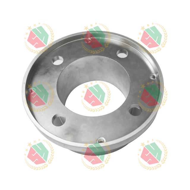
Material selection dictates the ultimate success of your manufacturing run. ADC12 serves as the undisputed industry standard for general-purpose casting. It functions as the direct equivalent of the widely used A380 alloy. This material offers excellent castability and superior dimensional stability. It flows effortlessly into complex, thin-walled molds without freezing prematurely.
Manufacturers frequently specify ADC12 aluminum die casting parts for automotive brackets, electronic enclosures, and power tools. It provides an optimal balance of mechanical properties and production efficiency. The alloy strongly resists hot cracking during the cooling phase. It also maintains impressive structural strength at elevated operating temperatures, making it highly versatile for standard commercial applications.
Specific operating environments demand superior corrosion resistance. LM6 meets this stringent requirement through its exceptionally high silicon content, typically ranging from 10% to 13%. This unique chemical composition provides maximum fluidity during the high-speed injection phase. It easily fills intricate, highly detailed castings without premature freezing.
Because it lacks copper, LM6 aluminum die casting parts excel in harsh, unforgiving conditions. Engineers routinely select this alloy for marine hardware, outdoor lighting enclosures, and chemical processing equipment. It withstands prolonged exposure to moisture and salt spray without degrading. While slightly harder to machine than standard ADC12 due to the high silicon, its long-term durability in corrosive environments remains unmatched.
High-stress applications require alloys prioritizing ultimate tensile strength and ductility. A356 delivers these critical characteristics alongside excellent pressure tightness. Unlike standard commercial die casting alloys, A356 responds exceptionally well to T6 heat treatment. This controlled thermal processing significantly enhances its baseline mechanical properties.
Heat treatment alters the internal microstructure to maximize yield strength. Engineers frequently specify this material for critical structural components. For example, an A356 die cast aluminum flange is commonly used in aerospace assemblies or high-pressure fluid systems. The alloy absorbs sudden impact and resists metal fatigue under continuous dynamic loading, outperforming standard ADC12 in structural integrity.
Successful manufacturing begins with rigorous Design for Manufacturability protocols. Uniform wall thickness is absolutely critical. It promotes even cooling across the entire geometry of the part. Inconsistent walls lead to severe warping, internal stress concentrations, and shrinkage defects. Keep all transitions between thick and thin sections gradual using generous radii. Standard wall thicknesses generally range from 1.5mm to 2.5mm.
Draft angles are equally important for production viability. Define minimum draft angle requirements based on your alloy selection and the depth of draw. Typically, a 1° to 2° draft per side is strictly necessary for internal walls, while external walls may require slightly less. This taper ensures clean, repeatable ejection from the mold cavity. It prevents deep scoring on the part surface and allows identical batch-to-batch replication.
Gas and shrinkage porosity represent inevitable challenges in high-pressure processes. Trapped air and shrinking metal create microscopic internal voids. You must actively manage and mitigate these structural defects through smart tool design. Vacuum-assisted systems evacuate ambient air from the cavity mere milliseconds before injection, drastically reducing gas porosity.
Optimized gating and venting designs direct turbulent airflow out of the mold. Strategic placement of overflow wells captures the very first wave of injected metal. This initial metal front often contains the most impurities, oxidized aluminum, and trapped gas. By pushing this degraded metal into the disposable overflows, the main cavity retains dense, structurally sound aluminum. Chill blocks can also be integrated into the venting system to freeze the metal instantly before it escapes the die.
Smart core design significantly reduces overall material usage. Cores create internal cavities and eliminate heavy mass areas within the part. Thick sections cool much slower than surrounding areas and cause localized shrink defects. By coring out these problematic areas, you maintain uniform wall thickness and speed up the overall cycle time.
However, you must carefully evaluate the necessity of undercuts. Undercuts prevent a part from ejecting straight out of the mold halves. They require expensive sliding cores, hydraulic pulls, or secondary machining operations. Eliminate undercuts whenever possible during the design phase. This reduces tooling complexity, lowers initial capital expenditure, and minimizes cycle times.
High initial capital expenditure defines this specific manufacturing method. Precision-machined, hardened H13 tool steel dies require significant upfront investment. You must calculate the exact break-even point compared to alternative fabrication methods. The process becomes highly economical at production volumes exceeding 10,000 units. Rapid cycle times and extremely low per-part costs quickly offset the initial tooling expense.
Consider the expected lifespan of the dies during your ROI calculations. Standard molds typically last for 50,000 to 100,000 shots. Thermal fatigue, known in the industry as heat checking, eventually degrades the die surface due to the constant expansion and contraction. Proper preventative maintenance, stress relieving, and strict thermal management extend tooling life and protect your investment.
Comparing manufacturing methods clarifies the best path forward for your specific project requirements. Understanding the limitations of each process prevents costly pivots later in production.
Manufacturing Process | Surface Finish Quality | Dimensional Tolerances | Ideal Volume Threshold | Complexity Handling |
|---|---|---|---|---|
High-Pressure Die Casting | Excellent (Smooth, uniform) | Tight (±0.002 in/in) | High (>10,000 units) | High (Near-net-shape capability) |
Sand Casting | Rough (Requires heavy machining) | Loose (Variable shrinkage) | Low to Medium | Moderate (Limited thin walls) |
CNC Machining | Excellent (Precision milled) | Very Tight (Micron level) | Low (Prototyping/Small batch) | High (But massive material waste) |
Investment Casting | Very Good | Moderate to Tight | Medium | Very High (Complex internal voids) |
Sand casting offers significantly lower tooling costs but requires extensive secondary machining to achieve tight tolerances. CNC machining provides exceptional precision but suffers from high material waste and slow cycle times. High-pressure injection delivers near-net-shape efficiency for complex geometries at mass scale.
Strict quality control guarantees long-term part integrity. Critical structural components require comprehensive non-destructive testing (NDT). X-ray inspection detects internal gas pockets and hidden shrinkage porosity that compromise mechanical strength. Dye penetrant testing reveals microscopic surface cracks entirely invisible to the naked eye.
Dimensional verification is equally vital for assembly compatibility. Use a Coordinate Measuring Machine (CMM) to confirm all critical tolerances. The CMM uses a touch probe to map the physical part against the original CAD model. This ensures the cast product remains identical to the original specifications. Consistent, documented inspection protocols prevent defective parts from ever reaching your final assembly line.
Selecting the right manufacturing partner mitigates severe production risks. Evaluate machine tonnage capacity first. The vendor must have presses that match your part size and required clamping force. Insufficient tonnage leads to excessive flash and dimensional inaccuracies across the parting line.
Verify all relevant ISO certifications. ISO 9001 demonstrates baseline quality management practices. IATF 16949 is strictly mandatory for automotive applications. Assess their in-house tooling maintenance capabilities and die repair protocols. Avoid vendors lacking automated process controls. Automated ladling, robotic sprayers, and die temperature control units are essential. Manual processes lead to inconsistent batch quality and severe thermal variations.
Engage a manufacturing partner early in the design phase to conduct a comprehensive DFM review and mold flow simulation.
Select your alloy based strictly on environmental exposure and mechanical load requirements to prevent premature part failure.
Audit potential vendors for automated process controls and sufficient machine tonnage to ensure consistent batch-to-batch repeatability.
Request a detailed tooling quotation that outlines die lifespan, maintenance schedules, and the specific H13 steel grade used.
Establish clear inspection criteria, including X-ray and CMM requirements, before signing off on the first article inspection.
A: Molten aluminum aggressively attacks and dissolves the submerged steel pumping mechanisms used in hot chamber machines. This chemical reaction destroys the equipment rapidly. To prevent this, aluminum requires a separate refractory melting furnace. The molten metal is then ladled into a cold chamber injection sleeve for each cycle.
A: Minimum wall thickness depends on the specific alloy and overall part size. Generally, thicknesses range from 1.5mm to 2.5mm. This ensures proper metal flow and fills the cavity completely before the aluminum solidifies. Thinner walls risk incomplete fills and cold shuts.
A: Standard high-pressure alloys like ADC12 contain significant silicon. Silicon does not anodize well, turning dark or mottled during the process. If cosmetic anodizing is required, you must specify low-silicon alloys. Alternatively, use surface finishes like powder coating or painting for better cosmetic results.
A: Porosity stems from two main sources. Gas porosity occurs when high-speed injection traps air or vaporized lubricant gases inside the metal. Shrinkage porosity happens when thick part sections cool unevenly, causing the metal to contract and leave microscopic internal voids.
A: The standard industry baseline for an H13 steel mold is 50,000 to 100,000 shots. Tool life heavily depends on rigorous die maintenance, operating temperatures, and the specific aluminum alloy being cast. Thermal fatigue eventually causes heat checking on the die surface.
A: ADC12 offers superior castability, making it the standard choice for complex, high-volume parts with intricate details. A356 provides higher strength, excellent ductility, and is heat-treatable (T6). A356 is specified for critical structural components requiring pressure tightness and fatigue resistance.


